Item Details
Product Description
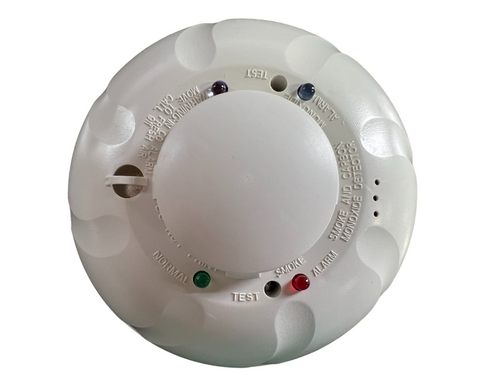
2-wire devices allow loop testing via the EZ Walk feature where wiring can easily be verified by checking the LED status at each detector. Smoke sensitivity can be easily measured using the wireless SENS-RDR device. CO cell functionality can also be quickly validated in the field with canned CO per NFPA 720: 2009 requirements using the detector’s RealTest® functionality.Features & Benefits:
- Compatible with a wide range of control panels with the use of the required i4Interface Module
- Sends distinct smoke and CO signals to the panel
- Sounds Temporal 3 for smoke and Temporal 4 for CO
- Built-in 85dB sounder
- LEDs display both CO and smoke status
- External IR LED provides extended range sensitivity testing
- Versatile mounting allows for wall or ceiling placement
- Easily replaceable electrochemical CO cell with 10-year end-of-life timer that signals the panel and chirps to alert the homeowner
- Drift compensation and smoothing algorithms provide false-alarm immunity
- Compatible with SENS-RDR sensitivity tester
Certifications:
- UL Listed S268
- CSFM 1653:0227
COSMOD2W Interface Module Specification Architectural/Engineering Specifications The i4 module shall be a System Sensor i4 Series model number COSMOD2W listed to UL 864 and UL 975 for Control Units for Fire Protection Signaling Systems. The module shall include provisions for mounting to 4-inch square back box. Wiring connections shall be made by means of SEMS screws. The module shall provide 4 LED indicators that blink or illuminate to indicate communication status, maintenance alert, alarm or freeze trouble conditions, and EZ Walk loop test mode (2-wire module only). The module shall allow communication to i4 Series and i3 Series detectors with any UL 864- and UL 975-listed fire alarm control panel capable of utilizing this module. The 2-wire module shall offer provisions for Style D wiring on IDC loops and shall provide a loop testing capability (EZ Walk) to verify the initiating loop wiring. Electrical Specifications The Operating Voltage shall be; Nominal: 12/24V non-polarized, Minimum: 8.5V, Maximum: 35V power limited. The Maximum Ripple Voltage shall be 30% peak to peak of applied voltage. The Standby Current shall be 62 mA maximum. The Maximum Alarm Current shall be 174 mA (module current only, does not include reverse polarity draw from attached detectors). The Alarm Contact Ratings shall be 100mA @ 36VDC, resistive. Physical Specifications The COSMOD2W dimensions shall be 6.04 inches (140 mm) diameter; 6.04 inches (154 mm) height; 1.0 inches (25.4 mm) depth. The approximate weight shall be 9.6 oz. (272 grams). The COSMOD4W detector Operating Temperature Range shall be 14°F–122°F (-10°C–50°C). The COSMOD2W Operating Humidity Range shall be 5 to 95% RH noncondensing.. The COSMOD4W Input Terminals shall be 14–22 AWG. The loop wiring resistance shall be 50 Ohms. Mounting options for the COSMOD4W include; 4-11/16˝ square back box; or placement inside a metal enclosure. LED Modes At Power up, the Green LED shall blink every 5 seconds. In Normal (standby) mode, the Green LED shall blink every 5 seconds; the Yellow LED shall be off; the Red LED shall be off; the Blue LED shall be off. In Smoke Alarm mode, the Green LED shall be off; the Yellow LED shall be off; the Red LED shall be solid; the Blue LED shall be off. In CO Alarm mode, the Green LED shall be off, the Yellow LED shall be off ; the Red LED shall be off; the Blue LED shall be solid. In Smoke Alarm and CO Alarm mode, the Green LED shall be off, the Yellow LED shall be off; the Red LED shall be solid; the Blue LED shall be solid. In Smoke Trouble mode, the Green LED shall blink every 5 seconds; the Yellow LED shall be off; the Red LED shall blink every 5 seconds; the Blue LED shall be off. In Smoke Freeze Trouble mode, the Green LED shall blink every 5 seconds; the Yellow LED shall be off; the Red LED shall blink every 10 seconds; the Blue LED shall be off. In CO Trouble mode, the Green LED shall blink every 5 seconds; the Yellow LED shall be off ; the Red LED shall be off; the Blue LED shall blink every 5 seconds. In Loop Wiring Fault condition, the Green LED shall be off; Yellow LED shall be solid; ;the Red LED shall be off; the Blue LED shall be off. In EZ Walk Test mode, the Green LED shall blink every 5 seconds, the Yellow LED shall blink every 5 seconds, the Red LED shall be off; the Blue LED shall be off.


